Decision 1Describe the features that select direction
Provide the pin drawing with diameter, length, head, chamfer, groove and tapered-end details. State whether either end may lead or whether a specific feature determines insertion direction. Very similar end forms can be difficult to distinguish mechanically. Use actual production samples to decide whether tooling alone establishes orientation or whether another verification step is needed.
Decision 2Challenge crossing and bridging in bulk
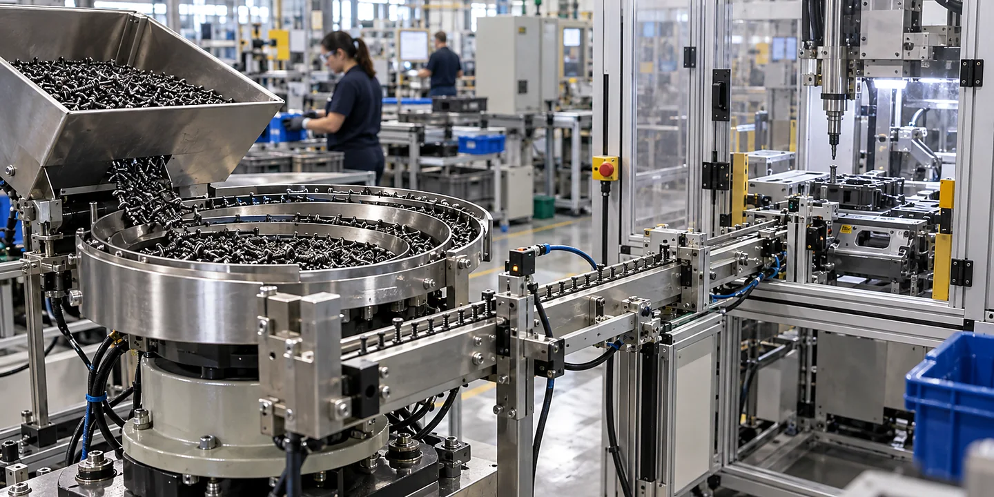
Include normal loading quantities and the condition in which pins arrive from the supplier. Long slender pins may bridge or form crossed groups, while oil or surface variation may alter movement. Observe these behaviours during refill and low-level operation. A brief run using a few manually separated pins does not demonstrate the intended bulk-feeding duty.
Decision 3Keep the track and release geometry together
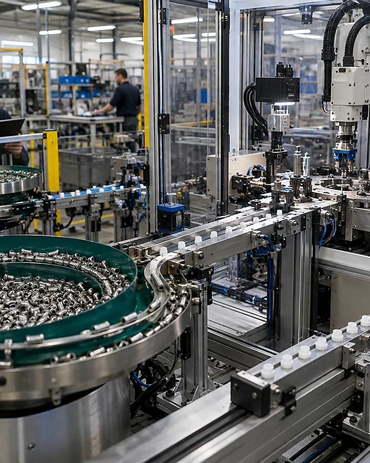
The final track must support the pin until the receiving tool can control it. Review gaps, changes in height and opportunities for the pin to roll or tilt. Describe whether the outlet feeds a nest, gripper, tube or insertion head. The correct choice depends on the required final datum and the part condition, not just available space.
Decision 4Detect absent or doubled deliveries
Define the signals needed before the next assembly cycle begins. A part-present sensor may not by itself distinguish one pin from two overlapping pins, so challenge the actual failure cases. Agree the response to a missing, reversed or doubled part. Include how rejected or uncertain components are cleared without losing the state of the receiving machine.
Decision 5Protect straightness and end condition
Identify limits for scratches, burrs, bent pins and damage to functional ends. Compare incoming samples with parts collected after a sustained trial. Tooling contact, recirculation and the final stop all deserve review. If straightness or surface condition needs a separate measurement, specify that method rather than assuming successful movement through the feeder proves part quality.
Decision 6Test demand and recovery at assembly
Run the proposed feeder against the receiving cycle, including normal pauses, a full buffer and replenishment. Record accepted presentations, interventions and damage alongside output. For multiple lengths or diameters, identify change parts and first-off checks. The final acceptance point should be the pin ready for insertion at the agreed datum, not the mouth of the bulk feeder.